Circuits
An electronic circuit is a closed path or interconnection of different electronic components and two terminals (positive and negative/ground) of a power source. There should always be an uninterrupted path between the two ends of the power source, otherwise the circuit will be incomplete and the components will not work.
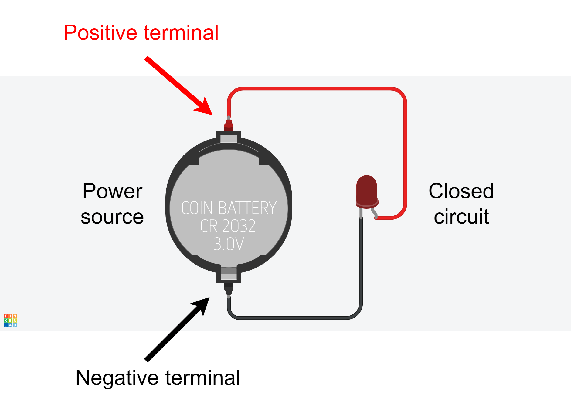
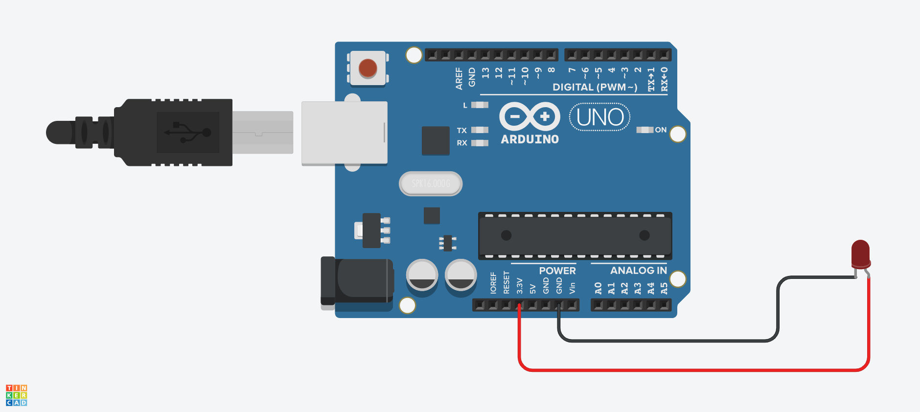
The Arduino board can also act as a power source and we establish the connections similar to the circuit above by using the 3.3v or 5v as the positive terminal and the GND pin as the negative terminal.
Sensors and actuators
Other than the Arduino as a power source, there are a variety of other components we generally use in our circuits. They can broadly be categorized into the following groups:
Sensors: Components that capture some information from the environment and transfer it to the Arduino board in an electronic format.
Example: A button, a temperature sensor, a distance sensor, a humidity sensor
Actuators: Components that display, demonstrate or represent some information from the Arduino on the environment.
Example: LED, motors, buzzer
Other than sensors and actuators, the circuits we will build will also include other components like a resistor. These don't fit in either category and are used as part of the circuit to enable both sensors and actuators to work.
Analog and Digital signals
Electronic signals, the way data is represented electronically, can take two forms:
Digital: Signals that can only have two possible states or values: High or Low, On or Off, True or False. These are also called binary.
Analog: Signals that can have a continuous range of states or values: 0 to 255 and 0 to 1023 which are the ranges we can write to actuators and read from sensors, respectively.
It is important to determine and be mindful of the type of signal in our circuit since both sensors and actuators can be of both types. So, when manipulating them (receiving or sending data) we need to do so according to the appropriate signal.
The breadboard
When creating our circuits, we can simply connect wires between our components or use a device that facilitates the organization of these connections.
Suppose we need to power two LEDs using the Arduino board. To do so, we can simply establish the necessary connections using wires.
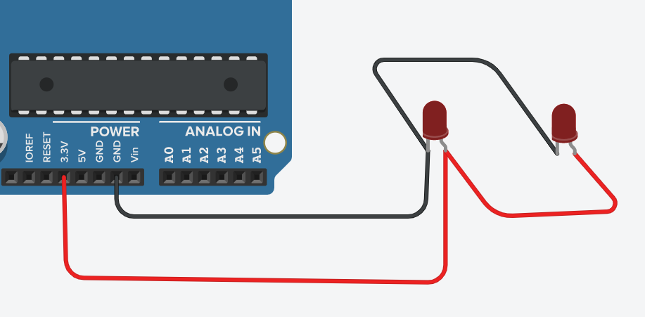
However, these connections can quickly become difficult to manage and to understand with an increase in the number of components in our circuit. To avoid the confusion or better manage the connections, we can use breadboards.
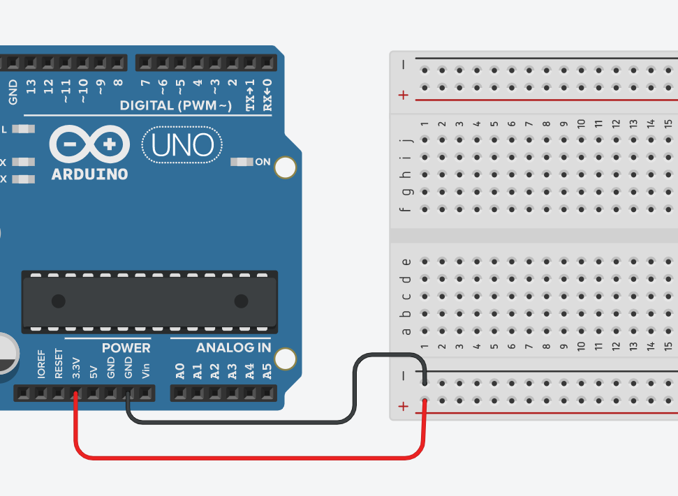
In a breadboard, we have rows and columns of interconnected points. In the image above, each point in the last row (in red) will be connected to the 3.3v pin from the Arduino board. Similarly, each point on the row before the last (in black) will be connected to the GND pin.
In the middle of the board, the interconnections change orientation. We have two sets of interconnected points forming distinct columns a to e and f to j.
This way, to connect our two LEDs, we just need to place them on the breadboard with each terminal in a different column. Next, we connect the column with the negative terminal of the LED to the row connected to GND. We do the same for the positive terminal and repeat for the other LED.
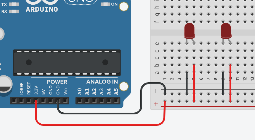
Seems confusing? Don't worry. You will understand it better with practice